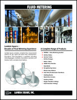
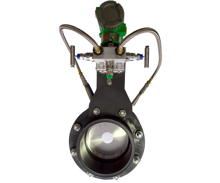
The ORIPAC Series is a complete orifice plate flow measurement package incorporating an orifice plate with a unique holder or carrier ring containing metering taps and integral gaskets.
Download ORIPAC Model 5300 information in PDF format.
Download ORIPAC Model 4150-T information in PDF format.
Unlike a standard orifice plate, the ORIPAC is a true primary element and includes components for differential pressure measurement.
Engineering, design and application support.
Fabricated to your requirements.
Differential flow metering for over 35 years.
Thousands of worldwide installations.
Use With: |
Model 5300 |
Model 4150-P |
Model 4150-T |
|---|---|---|---|
| Steam Measurement | Y | ||
| High Pressure Liquids | Y | ||
| High Pressure Gases | Y | ||
| Low Pressure Liquids | Y | Y | |
| Low Pressure Gases | Y | Y | Y |
| Corrosive Liquids | Y | Y | |
| Corrosive Gases | Y | Y | Y |
| Clean, Low Pressure Gases | Y | Y | Y |
| Clean, Low Pressure Liquids | Y | Y | Y |
ORIPAC Flow Measurement Systems have been designed for use wherever there is an application for a conventional flow orifice plate. They can also be used in place of other primary differential producers for efficiency and cost effectiveness. ORIPAC was designed and developed by engineers experienced in the differential flow measurement field.
Standard size units available from stock and customized units are available to meet specific field requirements including flange rating, pipe schedule and differential pressure. Installation is accomplished simply by slipping the self-centering ORIPAC between standard flanges (orifice flanges are not required).
The ORIPAC is available for all line sizes and fluids, and meets or exceeds AMSE, AGA and ISO standards.
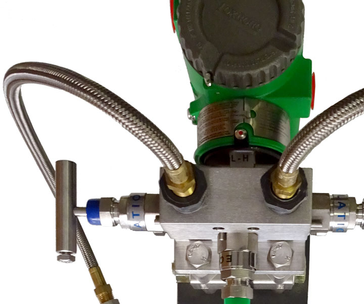
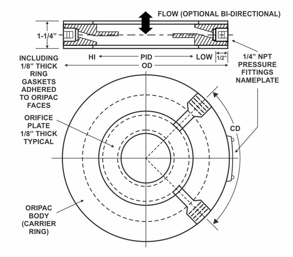
Integrated metering taps properly located and predrilled – Used with standard ANSI flanges - orifice flange unions eliminated. No drilling/tapping pipe.
Full faced integral gasket pre-attached – Precludes potential alignment problems during installation.
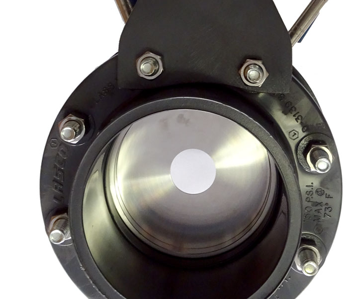
Self-centering within standard flanges – ORIPAC O.D. sits snug within bolt circle of specified flange rating insuring concentricity - centering devices or additional components eliminated.
"Corner" type metering taps – Established coefficient accuracy values.
Solid-state PVC construction – Use or superior high-tech materials eliminating rusting and plugging of sensing ports.
Custom Manufacture (able to meet specific temp and pressure requirements) – Standard configurations available from stock, custom units available in different materials, thickness and configuration to meet specific requirements for harsh applications.
Proven through a wide and varied range of applications and installations since 1984 – Ten (10) year history of reliability and accuracy.
Sized for specific pipe schedules or special inside pipe diameters including US/Metric, etc – Insures accuracy by eliminating pipe inside diameter to ORIPAC inside diameter mismatches.
Available with any bore size to produce any specific differential pressure – Ability to match range on an existing d/p transmitter or indicating gage without recalibration or replacement.
Orifice bore calculated to match specified "headloss" requirements – Exact differential pressure values and overall system head loss can be calculated and pre-determined.
Orifice bore styles available include Concentric, Eccentric, Segmental, Quadrant edge, multiple bore – Able to address challenging flow applications including: low viscosity fluids, gasses containing liquids, limited pipe runs, etc.
Drain hole at bottom or vent hole at top available for orifice plate. Additional tap can be installed for drainage purposes – Orifices may require a drain at bottom of orifice to allow passage of condensate. Air in liquid lines may require a vent hole at top of orifice.
Bi-directional flow capabilities – Orifice plate available without bevel to accommodate flow in both directions.
Orifice plate thickness option – Thickness of orifice plate provided according to ASME/AGA specs standard. Can be provided with special plate thickness to address high pressure lines, thick bore "critical flow" requirements, etc.
Available for any flange material or rating (125/150#, 250/300#, 600#, 900#, 1500#, 2500#) DIN Ratings or custom flange requirements – Eliminate potential flange rating mismatches, no need for additional centering devices - ideal for use within lightweight duct flanges.
Ideal for light weight duct measurement – Mounts between thin angle or plate flanges for lightweight installation.
Can be used within cast iron standard flanges. (Orifice flanges not available in cast iron) – Simple orifice device now available for cast iron piping without welding.
Can be sized for restriction or pressure drop control in conjunction with flow measurement – Eliminate additional throttling valve by combining flow meter and restrictor as one integral unit.
Port size (Pizometer through hole) can be increased if required – Reducing the chance of plugging in lines containing particulates, solids, etc.
Metering Taps drilled "straight through" to the pipe I.D. – Easily accessible and cleaned using pipe cleaner or rod out kit.
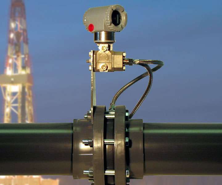
Can be used with Lambda flange mount bracket for installing instrumentation – Option for direct mount installation of manifold transmitter or indicating gage offering consolidated installation (Remote mount also available).
Pre-attached nameplate – Serial #, Tag #, ID, Bore and other information available. Also available: SS attachment w/SS wire or w/RTJ type nameplate holder.
Flexible readout options – Can be used with any Transmitter, Gage, Manifold arrangement.
Standard valve kit available – Includes nipples and shutoff valves to streamline installation.
All standard dimensions are designed for 150# Rated ANSI Flanges but can be customized as required.
| Line Size (D) | OD | Pipe ID | Tap Location (CD) |
| 0.25 | 1.890 | 0.364 | 4.5 |
| 0.50 | 1.890 | 0.622 | 4.5 |
| 0.75 | 2.250 | 0.824 | 4.5 |
| 1.00 | 2.625 | 1.049 | 4.5 |
| 1.25 | 3.000 | 1.380 | 4.5 |
| 1.50 | 3.375 | 1.610 | 4.5 |
| 2.00 | 4.125 | 2.067 | 4.5 |
| 2.50 | 4.875 | 2.469 | 4.5 |
| 3.00 | 5.375 | 3.068 | 4.5 |
| 4.00 | 6.875 | 4.026 | 4.5 |
| 5.00 | 7.750 | 5.047 | 4.5 |
| 6.00 | 8.750 | 6.065 | 4.5 |
| 8.00 | 11.000 | 7.891 | 4.5 |
| 10.0 | 13.374 | 10.020 | 4.5 |
| 12.0 | 16.125 | 12.000 | 4.5 |
| 14.0 | 17.750 | 14.000 | 4.5 |
| 16.0 | 20.250 | 16.000 | 4.5 |
| 18.0 | 21.625 | 18.000 | 4.5 |
| 20.0 | 23.875 | 20.000 | 4.5 |
| 24.0 | 28.25 | 24 | 4.5 |
NOTE: Dimensions based on 150# flange rating and standard schedule pipe
GENERAL:
This specification describes a differential pressure type of metering primary for the main line metering of liquid, gas or steam in a _____" pipe. The orifice plate flow meter "ORIPAC Model 5300" wafer type unit shall include high & low metering taps utilizing a "corner tap" configuration. Orifice primary shall meet or exceed ASME requirements for corner style metering taps with regards to accuracy, tolerances & calculations. A flow vs differential pressure curve shall be provided for each set of flow conditions.
MOUNTING:
The orifice metering primary shall be suitable for installation between standard ANSI flanges (any rating/material) mounted on standard pipe (any material). The unit shall be "self centering" within the bolt circle of the flanges. No alignment of the orifice shall be necessary. Drilling and or tapping of the main or flanges will not be allowed or required. The overall laying length shall be 1.25" including pre-attached ring type 1/8" thick Buna "N" Gaskets. Other gasket materials available upon request.
CAPACITY:
Normal flow rate of ____SCFM or ____ PPH or ____GPM at a differential pressure to be determined by Lambda Square Inc. at pressures & temperatures provided by engineer and calculated by Lambda Square Inc.
MATERIALS OF CONSTRUCTION:
The ORIPAC Model 5300 primary element shall be monolithic (single piece) constructed entirely of 300 series ss. Metering connections shall be 1/8" or 1/4" NPT female taps. Hose barb connections or extension nipples may be threaded to high & low pressure connections if desired.
ACCURACY:
The orifice primary shall be precision calculated, bored and bench calibrated to ASME & ISO specifications yielding a predictable accuracy of +/- 0.6 % of full scale flow. Calculations shall be performed by Lambda Square Inc. to determine exact differential & headloss at full scale & normal flow conditions. Calculation formulas shall be based on ASME guidelines. The orifice primary shall be tested under similar conditions for at least 20 years and shall be equal in all respects to ORIPAC Model 5300 as manufactured by Lambda Square Inc. of Babylon, NY.
METER PERFORMANCE:
Calculations for pressure loss may be performed in conjunction with the ORIPAC flow calculations by Lambda Square Inc. The overall pressure loss and differential pressure shall be determined at maximum & normal flow conditions. The permanent headloss shall be within the requirements of the application, and determined by the engineer in conjunction with Lambda Square Inc.
*Bolts should be 1.25” longer than standard make up flange bolts.
GENERAL:
Many of the installation problems associated with standard orifice plates have been eliminated by the use of the ORIPAC. Simply follow these instructions for an accurate and reliable meter.
PIPE REQUIREMENTS:
The orifice metering primary shall be suitable for installation between standard ANSI flanges (any rating/material) mounted on standard pipe (any material). The unit shall be "self centering" within the bolt circle of the flanges. No alignment of the orifice shall be necessary. Drilling and or tapping of the main or flanges will not be allowed or required. The overall laying length shall be 1.25" including pre-attached ring type 1/8" thick Buna "N" Gaskets. Other gasket materials available upon request.
INSTALLATION TIPS:
(a) If possible, do not install a valve upstream if it is going to be throttled. Install on the downstream a minimum of 6 diameters from the ORIPAC.
(b) The use of straightening vanes is not necessary for most applications.
ACTUAL INSTALLATION:
(a) Insert bolts through bottom half of the flange bolt circle.
(b) Slide ORIPAC between flanges (make sure arrow on ORIPAC faces in the direction of flow)
(c) Make sure pressure connections are properly positioned. ORIPAC can be installed vertically or horizontally. For horizontal liquid lines, install the ORIPAC with the connections on or under the horizontal center line. For horizontal air or gas lines, install with the connections on or above the horizontal center line. They should also be correctly oriented so as to not be blocked by bolts when remainder of bolts are inserted:
(d) Add rest of bolts and nuts leaving all bolts loose so ORIPAC is free to move.
(e) If necessary, the ORIPAC can be centered using a steel ruler to measure the total side to side movement and set Oripac at half way point all around.
(f) Lubricate & tighten bolts diametrically alternating to recommend flange torque.
(g) Check to insure the ORIPAC is installed with the arrow facing in the same direction as flow.